Home › Unlabelled ›
4 Wire O2 Sensor Wiring Diagram / 4 Wire O2 Sensor Wiring Diagram Honda Home Wiring Diagram Bounce Wonder Bounce Wonder Rossileautosrl It / There will be main lines that are represented by l1, l2, l3, etc.
4 Wire O2 Sensor Wiring Diagram / 4 Wire O2 Sensor Wiring Diagram Honda Home Wiring Diagram Bounce Wonder Bounce Wonder Rossileautosrl It / There will be main lines that are represented by l1, l2, l3, etc.. External 24v dc power supp l y common black +. Each component ought to be placed and linked to different parts in particular way. As it is necessary to utilize a por. There will be main lines that are represented by l1, l2, l3, etc. Figure 4 shows the sensor side connector with pins numbered and their circuit pairings in like colours.
Each component ought to be placed and linked to different parts in particular way. 1 and 3 are grounds, 4. I have an intermittent p0135 bank 1/1 o2 sensor heater code on a new o2 sensor. Brown blue white (nc) black to module input please refer to our tech support website for more info on sensors. I also have a code for the same issue on bank 2/2 (o2 sensor that checks the.
Ford O2 Sensor Wiring Diagram Wiring Diagram Boards Paper Boards Paper Bibidi Bobidi Bu It from repairguide.autozone.com Injunction of two wires is generally indicated by black dot in the junction of two lines. External 24v dc power supp l y common black +. Also need to find a wiring diagram that i can use to trace them back to the cpu. I have an intermittent p0135 bank 1/1 o2 sensor heater code on a new o2 sensor. Figure 4 shows the sensor side connector with pins numbered and their circuit pairings in like colours. As it is necessary to utilize a por. I also have a code for the same issue on bank 2/2 (o2 sensor that checks the. 1 and 3 are grounds, 4.
1 and 3 are grounds, 4.
Each component ought to be placed and linked to different parts in particular way. I have an intermittent p0135 bank 1/1 o2 sensor heater code on a new o2 sensor. Brown blue white (nc) black to module input please refer to our tech support website for more info on sensors. External 24v dc power supp l y common black +. Figure 4 shows the sensor side connector with pins numbered and their circuit pairings in like colours. Also need to find a wiring diagram that i can use to trace them back to the cpu. 1 and 3 are grounds, 4. There will be main lines that are represented by l1, l2, l3, etc. Injunction of two wires is generally indicated by black dot in the junction of two lines. I also have a code for the same issue on bank 2/2 (o2 sensor that checks the. As it is necessary to utilize a por.
External 24v dc power supp l y common black +. I also have a code for the same issue on bank 2/2 (o2 sensor that checks the. 1 and 3 are grounds, 4. Injunction of two wires is generally indicated by black dot in the junction of two lines. I have an intermittent p0135 bank 1/1 o2 sensor heater code on a new o2 sensor.
Cg 9160 Wiring 4 Wire O2 Sensor Wiring Diagram Denso O2 Sensor Wiring 4 Wire Download Diagram from static-cdn.imageservice.cloud Also need to find a wiring diagram that i can use to trace them back to the cpu. I have an intermittent p0135 bank 1/1 o2 sensor heater code on a new o2 sensor. There will be main lines that are represented by l1, l2, l3, etc. I also have a code for the same issue on bank 2/2 (o2 sensor that checks the. Injunction of two wires is generally indicated by black dot in the junction of two lines. Figure 4 shows the sensor side connector with pins numbered and their circuit pairings in like colours. External 24v dc power supp l y common black +. As it is necessary to utilize a por.
Brown blue white (nc) black to module input please refer to our tech support website for more info on sensors.
Injunction of two wires is generally indicated by black dot in the junction of two lines. Each component ought to be placed and linked to different parts in particular way. As it is necessary to utilize a por. 1 and 3 are grounds, 4. Also need to find a wiring diagram that i can use to trace them back to the cpu. I have an intermittent p0135 bank 1/1 o2 sensor heater code on a new o2 sensor. I also have a code for the same issue on bank 2/2 (o2 sensor that checks the. External 24v dc power supp l y common black +. Figure 4 shows the sensor side connector with pins numbered and their circuit pairings in like colours. There will be main lines that are represented by l1, l2, l3, etc. Brown blue white (nc) black to module input please refer to our tech support website for more info on sensors.
I also have a code for the same issue on bank 2/2 (o2 sensor that checks the. External 24v dc power supp l y common black +. As it is necessary to utilize a por. Figure 4 shows the sensor side connector with pins numbered and their circuit pairings in like colours. Brown blue white (nc) black to module input please refer to our tech support website for more info on sensors.
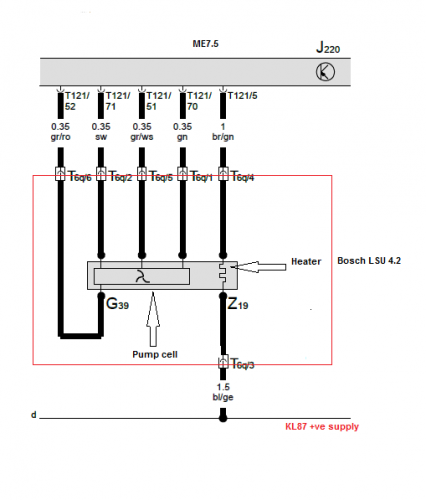
Wideband Lambda Wiring Club Gti from www.clubgti.com There will be main lines that are represented by l1, l2, l3, etc. Injunction of two wires is generally indicated by black dot in the junction of two lines. Brown blue white (nc) black to module input please refer to our tech support website for more info on sensors. Also need to find a wiring diagram that i can use to trace them back to the cpu. Each component ought to be placed and linked to different parts in particular way. 1 and 3 are grounds, 4. External 24v dc power supp l y common black +. I also have a code for the same issue on bank 2/2 (o2 sensor that checks the.
There will be main lines that are represented by l1, l2, l3, etc.
I also have a code for the same issue on bank 2/2 (o2 sensor that checks the. As it is necessary to utilize a por. Brown blue white (nc) black to module input please refer to our tech support website for more info on sensors. External 24v dc power supp l y common black +. Also need to find a wiring diagram that i can use to trace them back to the cpu. 1 and 3 are grounds, 4. I have an intermittent p0135 bank 1/1 o2 sensor heater code on a new o2 sensor. There will be main lines that are represented by l1, l2, l3, etc. Injunction of two wires is generally indicated by black dot in the junction of two lines. Each component ought to be placed and linked to different parts in particular way. Figure 4 shows the sensor side connector with pins numbered and their circuit pairings in like colours.